poepcba
 poe@pcbamake.com


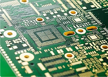
PCB impedance: the "highway toll booth" of electronic signals
Impedance control pcb is one of the core technologies to ensure the stable operation of electronic devices. It is like a toll booth on a highway, which directly affects whether the signal can pass smoothly.
1. PCB impedance
Impedance is the "comprehensive resistance" encountered by current in a circuit, which includes the combined effects of resistance, inductance and capacitance. For high-frequency signals (such as 5G, Wi-Fi, and HDMI transmission), the wires on the PCB are no longer simple "wires", but more like a complex transmission line. If the impedance does not match, the signal will reflect like hitting a wall, causing data distortion or loss.

2. The importance of impedance control
Signal integrity: High-frequency signals are extremely sensitive to impedance fluctuations. For example, if the impedance deviation of a USB 3.0 interface exceeds ±10%, it may cause a decrease in transmission rate or even disconnection.
Avoid interference: Impedance mismatch will cause signal reflection, induce electromagnetic interference (EMI), and affect surrounding circuits.
Equipment reliability: If the PCB impedance of mobile phones, routers and other devices is out of control, problems such as freezing, freezing or component overheating may occur.
3. Impedance control in PCB design
Designers achieve precise impedance by adjusting the following parameters:
Line width: The wider the wire, the lower the impedance.
Dielectric layer thickness: The thicker the insulation layer, the higher the impedance.
Material dielectric constant: High-frequency boards (such as Rogers RO4350B) are more stable than ordinary FR-4.
Reference layer distance: The distance between the signal line and the adjacent ground layer directly affects the impedance value.
For example, a microstrip line transmitting a 5GHz signal may need to control the line width to 0.15mm, the dielectric layer thickness to 0.1mm, and the error must be less than ±5%.
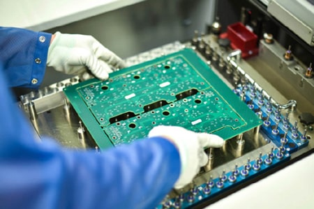
4. Challenges in manufacturing
PCB factories achieve impedance control through precision processes:
Etching accuracy: The line width error must be controlled within ±0.02mm.
Lamination uniformity: When laminating multilayer boards, the dielectric layer thickness must be highly consistent.
Test verification: Use **Time Domain Reflectometer (TDR)** to detect impedance to ensure that each batch meets the standards.
PCB impedance is the "invisible bridge" connecting design and manufacturing. From smartphones to satellite communications, precise impedance control determines the performance ceiling of electronic devices. In short: design sets the goal, manufacturing achieves the goal, and impedance determines success or failure.
If you have PCB/PCBA/OEM/ODM needs, please contact us, We will reply within 2 hours, and complete the quotation within 4 hours or less upon request.
Delivery Services

Verified by

Link Us on