poepcba
 poe@pcbamake.com


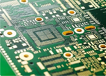
Characteristic impedance refers to the resistance of the high-frequency signal or electromagnetic wave in the propagation process of the transmission signal line relative to a certain reference layer at a certain frequency, which is also called characteristic impedance. It is equivalent to a vector sum of electrical impedance, inductive reactance, and capacitive reactance.
What's the point of making characteristic impedance pcb board?
Characteristic impedance is the core of solving signal integrity problems. With the continuous development of pcb electronic products towards high frequency and high speed, the circuit performance provided by PCB board must ensure that the signal does not reflect during the transmission process and keep the signal intact and undistorted. In order to ensure signal integrity, the characteristic impedance (Z0) of the signal line of the PCB must be matched with the "electronic impedance" of components; when electronic devices such as computers and communication switches are in operation, the signals sent by the drive components need to pass through the PCB The signal line reaches the receiving element.
Impedance-actually refers to the parameters of resistance and reactance, because the PCB circuit (board bottom) should consider plugging and installing electronic components, and the conductivity and signal transmission performance should be considered after plugging. Therefore, the lower the impedance, the better.


Under normal design components, the relationship between factors affecting impedance:
1: The thickness of the dielectric. Increasing the thickness of the dielectric can increase the impedance, and reducing the thickness of the dielectric can reduce the impedance; different prepregs have different glue content and thickness. The thickness after pressing is related to the flatness of the press and the pressing procedure; for any kind of plate used, it is necessary to obtain the thickness of the dielectric layer that can be produced, which is conducive to design calculations, and engineering design, pressing control, and incoming materials Tolerance is the key to media thickness control.
2: Line width, increasing the line width can reduce the impedance, and reducing the line width can increase the impedance. Line width control requires a tolerance of +/-10% in order to better meet the impedance control requirements. The gap of the signal line affects the entire test waveform, and its single point impedance is too high, making the entire waveform uneven, and the impedance line is not allowed to be compensated. The gap cannot exceed 10%. The line width is mainly controlled by etching control. In order to ensure the line width, according to the amount of etching side etching, light drawing error, and pattern transfer error, process compensation is performed on the engineering film to meet the line width requirements.
3: Copper thickness, reducing the line thickness can increase the impedance, and increasing the line thickness can reduce the impedance; the line thickness can be controlled by pattern electroplating or selecting a base copper foil of corresponding thickness. The control of copper thickness is required to be uniform. The shunt block is added to the thin wire and isolated wire board to balance the current to prevent uneven copper thickness on the wire and affect the extremely uneven copper distribution on the cs and ss surfaces. The board should be crossed to achieve the goal of uniform copper thickness on both sides.
4: Dielectric constant, increasing the dielectric constant can reduce the impedance, and reducing the dielectric constant can increase the impedance. The dielectric constant is mainly controlled by the material. Different boards have different dielectric constants, which are related to the resin materials used: FR4 boards have a dielectric constant of 3.9-4.5, which will decrease with the increase in frequency of use, and PTFE boards have a dielectric constant of 2.2- To obtain a high signal transmission between 3.9, a high impedance value is required, and thus a low dielectric constant is required.
5: Solder mask thickness, printing on the solder mask will reduce the impedance of the outer layer. The thicker the ink thickness, the smaller the resistance value.
POE is an OEM manufacture that focus on PCB & PCBA manufacturing over 24 years.We have the capability to manufacture pcb prototype ranging from basic single side boards up to 40 layer multilayers, and provide one stop turnkey services, including pcb layout,manufacture,assembly,components source,function testing services and so on.
If you have PCB/PCBA/OEM/ODM needs, please contact us, We will reply within 2 hours, and complete the quotation within 4 hours or less upon request.
Delivery Services

Verified by

Link Us on