poe@pcbamake.com


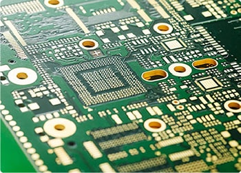
With the widespread adoption of new energy vehicles, charging stations have become critical infrastructure, where performance and reliability directly impact user experience. Among the core modules of charging stations, printed circuit boards (PCBs) play a vital role. From control systems to power management, PCB design and manufacturing determine the efficiency, safety, and intelligence level of charging stations.
Applications of PCBs in EV Charging Stations
1. Main Control System: The "Brain" of Charging StationsThe main control PCB manages overall operations, including:
These PCBs typically adopt high-density multilayer designs (6-8 layers), integrating high-performance processors (e.g., ARM Cortex series) with strong anti-interference capabilities.

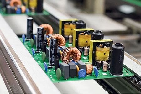
2. Power Management Module: Efficient Energy Conversion
The core function of charging stations is converting grid AC power to DC power suitable for EVs, especially in fast-charging stations (e.g., 120kW, 350kW), which handle high voltage (800V+) and high current (300A+).
These PCBs use heavy copper designs (≥2 oz) and high-temperature-resistant materials (e.g., aluminum substrates) to ensure stable operation under high currents.
3. Charging Interface Control: Critical Safety ProtectionWhen the charging gun connects to the vehicle, the PCB monitors in real time:
Displays, buttons, and indicators are PCB-driven, with some premium stations using flexible PCBs (FPCs) for curved screens.
Technical Features of PCBs in Charging Stations
1. High Power Density Design
Supports ultra-high currents (≥100A) in fast-charging stations (≥350kW).
Uses thick copper layers and plated through-holes to enhance current capacity.
2. Thermal Management
High thermal conductivity substrates (e.g., aluminum, ceramic) with heatsinks or liquid cooling for stable operation (-40°C to 125°C).
3. High Reliability & Longevity
Complies with IPC Class 3 standards for industrial environments.
Resists moisture, salt spray (coastal areas), and vibration (vehicle-mounted stations).
4. EMC/EMI Optimization
Multilayer PCBs isolate analog/digital/power sections.
Uses shielding layers and ferrite beads to suppress interference (meets CISPR 32).
5. Intelligence & Integration
Integrates current sensors (Hall effect), voltage sampling, and fault detection (e.g., leakage protection) to reduce external components.
Key Advantages of PCBs in Charging Stations
1. Enhanced Efficiency
Optimized layouts minimize losses (e.g., shortened high-frequency paths).
Achieves >95% efficiency with SiC/GaN devices.
2. Cost Reduction
Modular designs (e.g., integrated AC/DC and DC/DC) reduce PCB count.
Automated SMT production lowers labor costs.
3. Improved Safety
Built-in protection circuits (overcurrent/voltage, surge protection).
Isolation designs (opto-couplers, digital isolators) ensure user safety.
4. Rapid Iteration Support
Flexible PCBs adapt to various form factors (wall-mounted, standalone).HDI technology enables high-density routing for functional expansion.
5. Standardization & Compatibility
Supports multi-protocol communication (e.g., PLC for V2G).
Complies with UL 94 V-0 flame resistance and RoHS environmental standards.
Future Trends & PCB Requirements
1. Ultra-Fast Charging (800V+ Platforms)
Higher voltage insulation (e.g., 2500V).
Reduced parasitic inductance for high-frequency switching (SiC devices: ≥100kHz).
2. V2G (Vehicle-to-Grid) Support
Bidirectional charging PCBs with additional sensors and communication interfaces.
3. AI & Edge Computing
Integration of AI accelerators (e.g., NPUs) for predictive load management.
4. Miniaturization & Lightweighting
Embedded component PCBs for compact, portable charging solutions.
PCBs are the backbone of efficient, safe, and smart charging stations. As materials (high-frequency substrates), processes (3D-printed PCBs), and design tools (AI-optimized routing) advance, PCBs will drive the industry toward higher power, greater integration, and lower costs, shaping the future of EV charging infrastructure.
If you have PCB/PCBA/OEM/ODM needs, please contact us, We will reply within 2 hours, and complete the quotation within 4 hours or less upon request.
Delivery Services

Verified by

Link Us on