poepcba
 poe@pcbamake.com


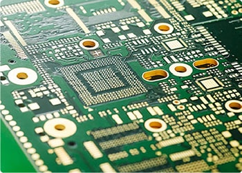
Tin beads refer to small granular solder that appears on the surface of the PCB or around components after welding during SMT processing. These small granular solders fail to adhere to the solder joints normally, but are scattered around the solder joints or on the surface of the PCB.

Solder paste quality problems: Inappropriate viscosity and particle size of solder paste may lead to uneven printing, thus causing solder balls.
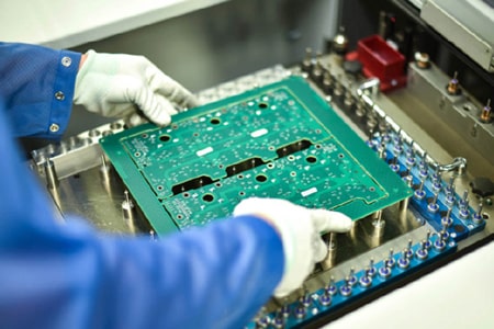
Poor patching
Component position offset: The patch machine is not accurate enough or the programming is wrong, resulting in the components not being accurately mounted on the pads, and the solder paste flows unevenly during welding, forming tin beads.Excessive patch pressure: Excessive pressure during the patching process causes the solder paste to be squeezed out of the pad area, forming solder balls.
Improper reflow process
Unreasonable heating curve: Improper reflow temperature curve, especially improper preheating and peak temperature control, will cause uneven melting of solder paste and form solder balls.
Oven environment problems: Uneven airflow or excessive pollutants in the reflow oven will also affect the melting and flow of solder paste, resulting in solder balls.
PCB design problems
Unreasonable pad design: Inappropriate pad size or too small spacing can easily lead to uneven distribution of solder paste and solder balls.
Pad surface treatment problems: Oxidation or unevenness of the pad surface affects the adhesion and melting of solder paste and increases the possibility of solder balls.
Prevention and solution measures
Optimize solder paste printing
Adjust printing parameters: Adjust the solder paste printing amount according to actual needs to ensure uniform solder paste thickness.
Improve steel mesh design: Reasonably design the steel mesh opening to ensure uniform distribution of solder paste.Choose high-quality solder paste: Use suitable solder paste to ensure that its viscosity and particle size meet the process requirements.
Improve patch accuracy
Calibrate the patch machine: Regularly calibrate the patch machine to ensure its accuracy and stability.Keep the soldering furnace clean: Clean the reflow oven regularly to ensure uniform and pollution-free internal airflow.
Reasonably design the pad: According to the specifications of components, design the appropriate pad size and spacing to ensure uniform distribution of solder paste.
Surface treatment: Ensure the quality of the pad surface treatment to avoid oxidation and unevenness.If you have PCB/PCBA/OEM/ODM needs, please contact us, We will reply within 2 hours, and complete the quotation within 4 hours or less upon request.
Delivery Services

Verified by

Link Us on