poe@pcbamake.com


Is it necessary to do DFM check before PCB production?
You will understand after reading this article!
As a PCB production supplier, we encounter customers asking every day: "Can't the design files be sent directly to the factory for production? Is DFM check necessary?" The answer is clear: it must be done!
DFM (Design for Manufacturability Check) is like a "PCB physical examination report", which can find out design risks before production and avoid failure after production. Let me tell you in plain language why DFM check is necessary and what it checks!

Why is DFM check necessary?
Save time and money: Is there a problem with the design? It was discovered after production, which may result in rework or scrapping, delaying delivery and burning money! DFM check finds problems in advance, and changing files is 10 times faster than changing physical objects!
Improve the yield rate: If the design is unreasonable (for example, the line is too thin and the hole is too small), the factory will do it anyway, and the yield rate will drop directly. DFM check adapts to the factory process to make production "smooth and unimpeded".
Avoid low-level mistakes: Pads miss windows? Silk screen covers solder joints? Solder mask error? These pitfalls will be revealed once DFM is checked!
Main contents of DFM inspection
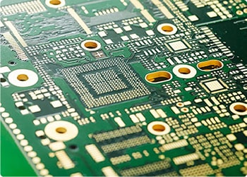
1. Basic design rules
Line width/line spacing: whether it meets the minimum processing capacity of the PCB factory (such as 4mil line width/line spacing).Layer alignment: whether the alignment deviation of each layer (circuit layer, drilling layer, solder mask layer) is within the allowable range.
Copper foil uniformity: avoid large area of copper foil causing PCB warping or uneven etching.
2. Solder mask and silk screen
Solder mask opening: whether to cover the pad to prevent welding short circuit or copper leakage.
Silk screen clarity: whether the text and logo are clear to avoid overlapping or covering the pad.
3. Drilling design
Hole spacing: avoid drilling cracks due to too small hole spacing (such as mechanical drilling spacing needs to be ≥0.3mm).
Blind buried hole design: whether it meets the factory's stacking process capabilities (such as laser drilling of HDI boards).
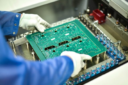
4. Panelization and process edges
Panelization method: whether to add V-Cut or stamp holes to avoid difficulties in separating boards.
Process edge width: whether to reserve enough clamping edges (usually ≥5mm) for equipment clamping.
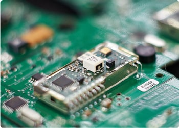
5. Component layout and welding
Component spacing: whether it meets the requirements of reflow soldering/wave soldering (such as SMD component spacing ≥0.5mm).
Heat dissipation design: whether high-power components dissipate heat reasonably (such as adding heat dissipation holes or copper foil).
Pad symmetry: avoid tombstones caused by asymmetric pads (such as small packages below 0402).
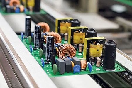
6. Materials and special requirements
Board selection: whether high-frequency boards, high-TG materials, thick copper boards, etc. meet the manufacturer's process capabilities.
Impedance control: whether the stacking design meets the impedance requirements (impedance calculation files must be provided).
7. Testing and reliability
Test points: whether sufficient ICT test points are reserved (diameter ≥ 0.8mm, spacing ≥ 2.54mm).
Thermal stress: whether there is a risk of delamination due to differences in thermal expansion coefficients.
Golden rules for DFM inspection
Factory docking requirements: ask the factory for process capability documents in advance (such as minimum line width, aperture, layer deviation accuracy).
Determine the standards for special requirements (impedance, immersion gold, blind buried holes)
Borrow inspection tools: use CAM350, Valor and other software to run automatic inspections, but don't rely entirely on machines, manual review is essential!
Provide complete files: Gerber, BOM, assembly drawings, none of them can be missed!
Special care is required for high frequency and high speed: impedance lines should not be randomly wound, reference layers should be complete, and equal length wiring should not be forgotten!
High frequency boards (such as Rogers) are difficult to process, so cooperate with the factory in advance!
DFM inspection makes design and production seamless. As a PCB supplier, we strongly recommend that you do a DFM inspection before production! It can not only avoid pitfalls and save money, but also enable the factory to produce efficiently. PCBAMake provides free online DFM inspection to find and solve problems in time, helping your project to be produced faster and better.
If you have PCB/PCBA/OEM/ODM needs, please contact us, We will reply within 2 hours, and complete the quotation within 4 hours or less upon request.
Delivery Services

Verified by

Link Us on