SMT Stencil
The purpose of an SMT stencil is to transfer solder paste to a bare PCB.
What stencil is?
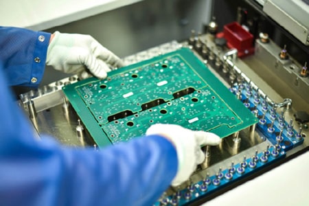
The purpose of an SMT stencil is to transfer solder paste to a bare PCB. A stainless steel foil is laser cut creating an opening for every surface mount device on the board. Once the stencil is properly aligned on top of the board, solder paste is applied over the openings. When the stainless steel foil is separated from the board, solder paste will remain, and the board is ready for placement of the SMD.
Material: INOX stainless steel SUS304
Mainly used Stencil Type:
- Laser cut SMT stencil. most common paste stencil type nowdays:
- Electroformed stencil, offer the best paste release characteristics and frequently used for fine pitch SMT applications such as BGA;
- Step stencil, with two or more different stencil thickness in a same steel plate. because different components have paste requirement:
- Nano Coated Stencils, very high precision of the opening position, Smart SMT Tools has leveraged its chemistry knowledge to develop unique nano coatings that improve various steps in the PCB Assembly process.
Regular size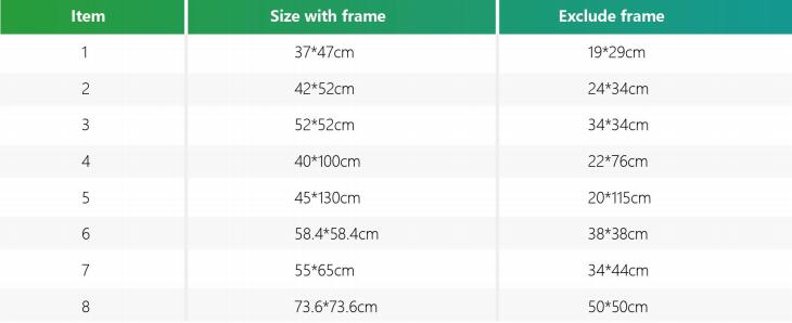
How to choose the suitable thickness of SMT stencils?
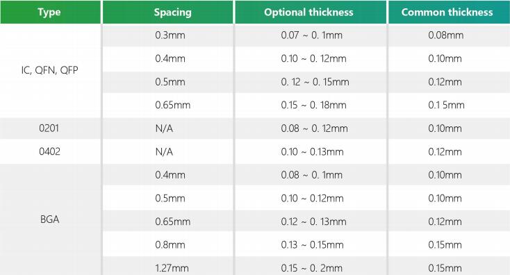
* This table is normally suited to solder paste stencil; for red glue stencil, the thickness is 0.18mm normally, please be aware of this.
How to inspect the quality of stencil:
- Size of the frame meets the requirements, the quality of taut mesh, the tauter,the better quality of printing.
- Check the appearance quality of the template mesh for obvious defects, such as the shape of the mesh, high density or narrow spacing of the pins adjacent to each other with no abnormalities.
- Use a magnifying glass or microscope to check whether the flare of the pad opening is downward, whether the inner wall around the opening is smooth, with or without burrs, focusing on checking the processing quality of the narrow-pitch IC pin opening.
- The product's printed board is placed on the bottom surface under the template, and the leakage holes of the template are used to align the printed board pad graphics, checking that the graphics are perfectly aligned, and that there are no multiple holes (unwanted openings) and fewer holes (missed openings).

